
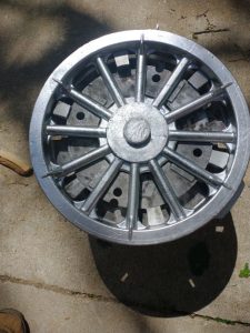
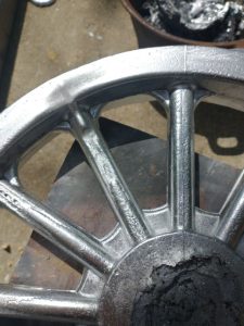
First Pour Bottom Cast Surface
By Robert Gamble
Diligent preparations were made, level of expectations were kept at bay, and the engineering mindset was put in full sway as the part was poured…with much anxiety.
The project: 14 inch diameter replica model – t go-kart wheel, being cast in a solid mold.
This is not our first rodeo, as we have cast many a wheel using sand casting, however, the sand casting method offers some benefits that solid molding does not, like ease of part removal (the sand just falls off!) and complete filling (gas pockets are not typically a problem – as sand is permeable.)
Preparations for the part were conducted in good fashion as all the unknowns were covered the best that was possible. In fact all those preparations paid off. It is just the “up pops the devil” that will get you every time, and that is where you learn.
To begin with the pour went well, no sudden expansions, the part was heated negating any sudden steam releases.
The release of the part however was problematic and not for reasons that I was expecting. (This is the learning part!)
For anyone who has ever used an acetylene torch or read a book about the X-15 rocket, they would appreciate what occurred with the part-mold interface.
Two things occurred, 1.) the intake runner had a sharp edge with flow going past it! (In retrospect – a no-no. No flow program would have caught that, other than showing there might be turbulent flow there, hence a temperature concentration and a blow out, or melting-melding of the part and the tool.
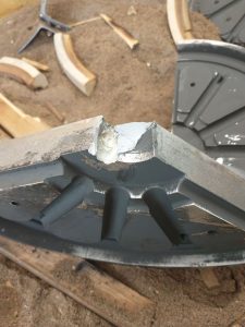
Intake Runner Eroded The Wall of The Filler Hole, like a blow torch!
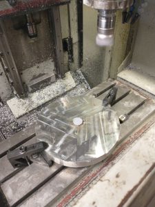
Face milling the filler neck off (Not optimum!)
2.) The filler neck was larger than the fill hole. This exacerbated the intake flow issue, causing more turbulent flow. But the silent killer, the intake runner could not be removed without ridiculous measures….yeah the CNC machine. (Not an optimum production method!)
The question is: Is there a fix? Or is this just ” If at first you don’t succeed…quit?!”
As Yoda would say “There is no quit, Only Do.”
There definitely are improvements and that is why we had our list in the beginning before we even started pouring…so lets go back to that list.
- Excessive shrinkage in the central hub
- Failure to release from the tool (not enough draft, or polish on tool surfaces)
- Failure to fill fully (tool is too cold)
- Failure to fill in all areas with potentials for air voids (ie bubble pockets – sand molds do not have this problem, as the sand vents the gases)
We composed this list as a Failure Modes Analysis, or Failures expectations. The question to ask yourself “If we composed this list, was there ever a hope for resolution in the beginning?”
The answer is “Yes, the reason we composed this list is to have plans in place for resolution.”
The idea is to not live in crisis mode here and be flummoxed by every bad outcome. Life is about managing crisis, not letting the crisis overrun everything.
So lets go through this list and see what happened.
1. Excessive Shrinkage in the central hub: actually the part rated pretty well. The central hub did break and that was because of other concerns.
2. The part released well from the tool, all the draft worked as expected and the part quality was really good from a surface finish standpoint. I was a little concerned that the surface finish of the part would look like zig-zag marks from a CNC machine, but for the most part it looks really good. Several past customers have comments on how good it looks.
Air pocket problems, venting required
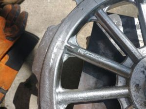
3. Failure to fill fully. This is an issue. Several of the arms did not fully fill and this may be combination of cold tooling and air pockets.
Gas venting problems. Air pockets in the tool prevent full filling. Vents are needed.
4. Failure to fill in all areas because of gassing. This is an issue, getting the gasses driven out will be problematic. I am guessing that when the tool heats up more evenly that wave-lines and gas pockets will be mitigated. However, definite gas release paths will be needed. I am working with mold experts at the moment to figure out what kind of gas release paths can be developed easily. Could be as simple as a couple of drilled holes. It should be noted that the gas and fill problems are only on the top half of the tool.
The problem of not getting the part off of the top half of the tool was a design error and that will be remedied easily by enlarging the intake port. This will serve several purposes, 1.) the knifed edge of the intake corner will be under the intake funnel, so turbulent flow will hit the edge of the intake port. 2. ) The intake runner now will be smaller that the intake port thus allowing easy removal of the upper half of the tool, it will slip up instead of being stuck in place.
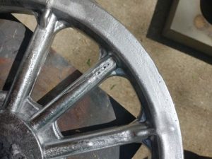
Gas Pockets, the gas had no where to go, poor venting
The upper casings will be modified in the next couple of days, and a second pour will be conducted shortly thereafter.
The overall process of getting the tool ready is kind of involved, as the tool must be preheated. The first intention was to immerse the whole tool set into a kiln, however the tool set is tool large in diameter. The final resolution was to place the assembly on top of the kiln for at least 45 minutes and then hit the whole tool with a large broad spreading torch. The final temp before pouring was approximately 180 – 200 degrees F. The upper half heated last.
And finally the temperature of the tool may have dropped significantly as the tool was placed to be poured. It took at least 10 minutes of prep time to get the tool fixed in place, this time lag may have effected the overall temp of the tool set.
The final assessment: success. The part came out well, had some minor set backs as far as releasing from the tool (but those are easy fixes), and some fill issues which need to be addressed with simple venting.