
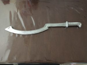
First Cast of an Egyptian Khopesh
The request was simple: “Make 3, no 4 new products for the up-coming fair.”
The notion of “Ready, Fire, Aim” is at work here. In the last article Breaking Into Small Markets in Two Weeks, we discussed the process for ascertaining if there is a market. In this article we will be discussing the actions taken to pursue the new market and the successes and failures we had along the way.
The “cat has been let out of the bag” as they say in this article where we pursue 3, nay 4, different sword designs and the most cost effective way to their production.
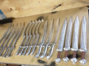
You may be wondering, why do I keep saying “nay 4?” Because we initially started out with 3 sword designs, but as the week progressed in tooling development, it was decided that after considering what the customers were doing with the swords (the hefting, the deep seated grins) the 4th sword, the Gladius got the most “googly eyed” reactions. So the Gladius, yeah and verily, was added to the line up!
Okay enough of the hype, onto the nuts and bolts of what actually occurred to make the swords.
To keep the process simple, the development of the sword follows this format:
- Find A Suitable Model
- Make a simple tool model
- Cut out the tool template
- Duplicate the tool template
- Make Mold of the Tool Template
- Cast Mold
- Test Mold
- Troubleshoot Mold
- Retest
- Finalize Process
That may seem like a long list, so the simple list is this:
- Find a suitable model and develop the tooling design off of this model
- Cut out a tool template and use this template to either make parts, or develop a hard tool (both are possible, making this a safe low risk option)
- Use the template to make hard tooling (or cast real parts using sand molds). Test the hard tooling to determine the flow patterns and possible final product issues (ie flow lines, voids-shrinkage, cracks…etc)
- Correct tool, or the process (ie add vents, heat up tool more, start over?!
Find a Suitable Model
As the title says “from picture to…” the first thing we did was peruse the internet for swords that fit our criteria. They had to be older swords and available for download in a 3-D CAD format.
All four swords were purchased from internet sources for download and then converted into CAD that was usable. What that means is the models were not CAD friendly at first and had to be converted so they could be processed by CNC software.
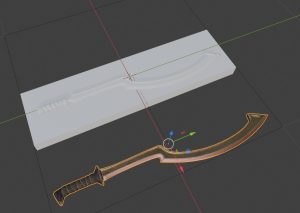
We at first used Blender to convert the files to STL, then used an on-line converter to make the STLs into STEPs. The STEPs are then – semi-usable for CAD software. This development process here took several days, as the concept that I was trying to do was taxing the software capabilities of the most advanced packages available today.
| As a side Note:
The impression most of us get is that a simple scan can be taken of a part and then used directly to make parts. This is true and it is false. The 3-D scanning process is primarily good for making 3-D shells or the scan of the external geometry of the part. However, and this is a big however, taking a part and developing the reverse or cavity images of the part are quite difficult for software of this age. The cavity images can be attained, but at a cost. And keep in mind we are on a budget and a time crunch. The big question is, “How do you develop a cavity image of a part, when all you have is a part image?” That is where Prototype Industries shines and can develop a tool using what is available to develop what seems unattainable. |
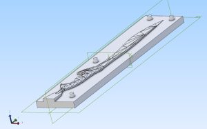
Design Tool off Of This Model
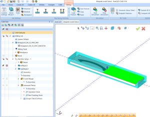
Once the models were found, a base template was developed so that the models could be dumped in and then machined. This format consisted of a 6″ x 28″ tool template. The question was what would the template be made out of? A cursory cost analysis of the tool in question was conducted and revealed a jaw dropping $1000 in material costs. Then on top of that, extensive machining would be required pushing the CNC mill in time as well as wear and tear.
Cut Tool Template
The target cost for a tool was something like $200 in materials. How would that even be possible?
Answer: Wood.
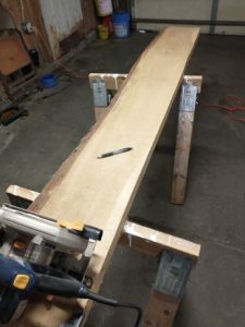
Fortunate for me, my neighbor owns a saw mill and had several hard wood boards he was willing to part with. We were able to procure several boards and started going to town.
As with every project I seem to get my hands on, there is some sort of barrier to entry. Some barrier that makes making the project complete…questionable at best. The boundaries of whatever I am dealing with are pressed. That means the 3-D printer is being asked to do things that 3-D printers don’t do, CAD software is being asked to do boolean operations that are not possible, CNC machines are being asked to go beyond their boundaries and machine stuff larger than they can possibly machine….
Thanks to the BobCad for their assistance and their product. It works seamlessly from model to machine.
Model development from STEP to final mold design
That is my lot in life, push, push, push…but it always seems to happen in the end. As John Paul Jones said (as all the sails and masts are torn off his ship) “I have not yet begun to fight!” That’s my projects in a nutshell!
You probably gathered that 28 inches is quite long. My CNC machine has a machining foot print of 17.7″ x 12.2″ x 16.1″. How is this going to be possible to machine something essentially 32 inches long?
With two set ups: I called them left and right to keep them separated. Figuring out the zero point was astonishingly simple, once the set up was in place.
For the non-symmetric swords, the Kopesh, the Falcata, and the Kopis, two different mold halves were required. That means a grand total of six different CNC cut-out templates for these swords. That means six different mold casts also. And this has to be done in less than two weeks.
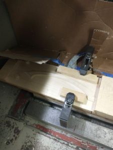
Left hand side machined, getting ready for right hand side
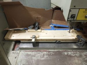
On the final run for the template, the right side being machined. (Sometimes the machine would run all night.)
I got it down to a process where a sword set could be done in a day, and that while the storms are raging outside. One day we had to shut down the mill because the hot summer days were causing brown-outs. The mill was constantly stalling on this run. Getting the swords done while attending to other projects was key. A sword wood template took a grand total of 9 hours to get the cosmetic finish fine, and require minimal sanding. (My days with Plastics Services as their Chief Tooling Engineer paid off here.)
Make Final Mold Using Template
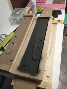
The final templates were brought into the model shop and lightly sanded to get the rough spots out. The halves would be prepped and then sand casts developed off of these templates. This proprietary process is what makes this conversion from positive model to negative model surface a unique system that we have developed to save customers extensive tooling costs especially when developing hard tooling.
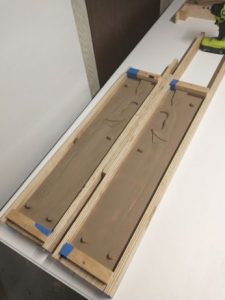
Templates being prepped for mold cavity transfer.
Sand duplicated cavity being readied for casting. An open face casting of this type is possible, however the excessive shrinkage from the non-uniform wall thickness will make the whole casting to warp.
Once the main cavity face has been developed into a sand casting mold, the option of open face casting is possible, but this is very risky as the shrinkage of the mold will yield warpage that is irrecoverable or not able to be bent out or machined out.
So a uniform wall thickness is desired to keep the warpage to a minimum. A trade secret of modern molders is to add a wall thickness to the mold by adding a layer of clay on to the mold surface. Once this clay is in place, a sand mold can be cast on the back side of the mold assembly. Once cured, the clay is removed and the mold is ready for casting.
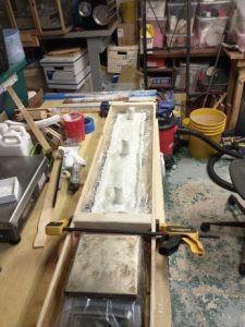
A layer of clay is added to the mold and then a sand layer is added to provide a full mold assembly. The clay is removed later.
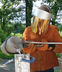
Once the mold is assembled, it is ready to cast. Just like any other mold, it is poured and extracted.
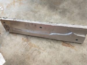
Mold hot off the casting line. Some minor de-flashing is required and then test of the tool.
Mold assembly fresh after casting (some minor leakage is acceptable to provide full mold fill and gas venting)
Pouring the mold is a simple process and extracting the part is equally as simple. Proper part design aids in proper filling and prevents excessive shrinkage. Large thick sections, such as the handle, are prone to shrinkage. Deciding on whether the shrinkage is acceptable is part of the development cycle.
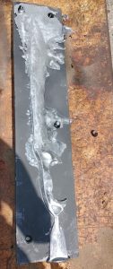 Observations of flow patterns and how the part is casting are shown here in the flow out flashing. Observations of flow patterns and how the part is casting are shown here in the flow out flashing.
The culprit in part failure here is not what you would expect. The flow out is actually a good thing as it allows the part to fill especially in the narrow sections. The cool down is what makes this part fail and it is because of the alignment pins not allowing the part to shrink. They cause a large lever arm putting stress on the part. Avoiding the alignment pegs is key along with proper venting. |
Because these molds are quickly developed, simple part changes can be made to aid in the design upgrades to get the product done quickly and to market.
As was stated earlier in the article “Ready, Fire, Aim.” What we have done here is essentially fired the product into the market or fired the design into the tool. These low cost entries into the market help develop a viable product, and also ascertain whether there even is a market.
The next step is presenting to market and see what happens!
Getting ready for the market!