
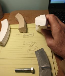
Hand sketched idea along with 3-d printed prototypes. Sand core sitting in the middle.
By: Robert Gamble
Kind of an interesting title “Solving Problems: That’s What We Do!” that actually is our forte, what we bring to the table at Prototype Industries.
With my vast work experience in developing over 40 different viable products and 25 patents to the back them up, I bring a can-do spirit to the table, the kind of attitude needed to fix problems and make unique solutions to problems that seem impossible to surmount.
In this article we will be discussing the Solid Cast Sand Core problem.
In the prior article we discussed the “groan factor.” The groan factor simply is acknowledgement of inefficiencies, or time-wasters in a process. We use it to access actual value for a product, how much effort and inefficiency is thrown at this product to make it? If the inefficiency is acceptable, we sometimes step ahead, but if the inefficiency is holding back the process significantly, then it needs to be addressed quickly.
Cores are the bane of the casting industry. That means they are tedious and require special equipment to adequately make them.
In case you are new to the casting industry, cores are what makes hollow parts “hollow” when casting. They fill the inside voids of castings and then are knocked out after the part is cast.
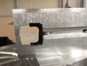
Sand Core placed in mold. This shape provides the profile needed for the tire and tube on the wheel.
There is a vast field of core design parameters that we will not address in this article, but it is sufficient to understand that cores are not an easy make, and also require special tooling.
Enter the world of sand cores for Model T go-kart wheel castings.
When the core was first developed it was made using sodium-silicate-sand stuffed into a two part 3-d printed mold. This worked moderately well, but it was as the workers put it “putt-see” or “groan worthy.” Removal from the mold was equally groan worthy as the parts would crack, not fill fully, or get stuck in the mold entirely. Curing the parts was problematic as well, proving to be very tenuous as many times cores would be extracted and not fully cured, falling to pieces on extraction….groan….!
Longer molds were developed to cut down the process of development, but the same issues still plagued the process. Changing to different types of sand binders helped, as well as adding release agents, but the same problems dogged the process.
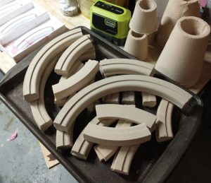
Sand cores waiting to be placed in the mold. To develop enough cores for a wheel it takes around 30 minutes.
Finally some relief was granted when a partial fill, or half fill system using silicone molds was developed, however the process was the same with different problems. Partial fills were not a problem now, and the actual core sections were coming out well, it just ate up real-estate (lots of table space) and required small batch runs to get the process going. Additionally, instead of having a full wheel core set done in 20 minutes, now it only provided half the wheel section three quarters, or 75% of a wheel core set in 20 minutes. To achieve a full wheel set in ideal conditions (meaning having 1 full wheel set with the new method) it takes 30 minutes to make a set, which means only 2 wheels can be made in an hour. The target is 10 wheels in an hour with the tool sets before us.
The cores are the hold up. They are the groan factor that needs to be put to rest.
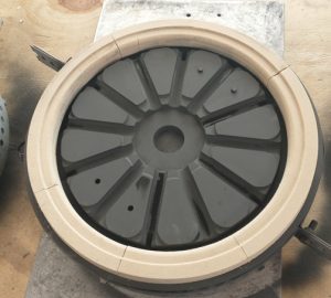
A fully cored mold, just prior to casting.
Enter the problem solving mindset of prototype industries.
It has been long posited that solid metal cores would solve the problem for the wheel casting. However, solid cores typically have draft, the ideal wheel design would not have draft, as this may cause the tires to leverage themselves out of the channel when put on the rim.
So the criteria was to either develop a rapid method for developing sands cores, such as a sand gun (which was developed and tried, took more time to load the gun! -or buy a special expensive rig), ram press, or even simple urethane molds, however, the solid core because it is not destroyed every time a part is made held the most promise.
The problem with the solid core is the mechanics of castings when they cool. When metal cools it contracts and acts like a clamp on anything inside it. That is why draft on cores is desired because the clamping force tends to eject the core, instead of clamping down hard and holding it.
Often in industry collapsible cores are designed especially if the wall sections need no draft or even have impossible reverse draft or recesses. These types of cores resemble a 3-d puzzle that has multiple pieces to change the solid shape to a moveable flexible shape.
That was the key to this project. Develop a collapsible core, that would not self eject out of the mold, but would eject with simple tools.
To tackle this problem a sample model was put together then 3-d printed. There are several unknowns in this design that required a hands on model to see how the model actually works.
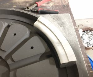
Simple 3-d printed cores were developed to explore the tapered core system. On the tablet are the initial sketches. These prototypes were made in less than a day to figure out the mechanism of the core.
As it turned out, two 3-d printed models were developed to find the sweet spot for the design. The unknown still sitting on the table was what would the effects of the cross-plane-cut be? The way the cut was made could prove to be a problem in the design. A longer larger core could be developed, for example, that would wrap 120 degrees, however the core removal may not occur as planned because the extraction planes may not actually be planer, but conical.
(Which in the end they are conical, however the conical-ness is so subtle it does not effect the overall performance of the smaller core.)
These unknowns had to be examined in real world samples, so hence the 3-d printing.
After the 3-d prints were examined and proved functional, a full blown sample was put together using the CNC milling machine.
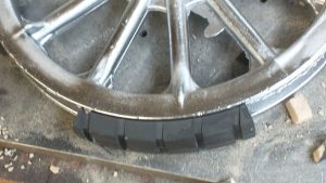
Machined prototype placed in the mold. A single prototype was developed to determine if the concept would work. This prototype proved the concept and also showed the problems with casting as a result.
A first cast sample was constructed and proved that venting was critical to the design. When die-casting it is important to understand that a wave of gas is in front of the flow and can get trapped in the mold if not vented properly.
So proper vents are required. The sand cores act as a semi-permeable vent, whereas the solid core acts as a shut door. Gas vents, generous ones are required when doing die casting.
For example in the sword casting exercise it was shown that venting by having a loose parting line allowed the flashing to behave like a vent. The goal for die casting is to minimize the amount of secondary de-flashing, so adding sensible vents is key.
The bottom line in this project is that the problem of sand cores was solved by making a suitable collapsible core system that in the end works superbly.
To understand the trouble shooting process by which the core was developed, stay tuned for the next article “Trouble Shooting a Collapsible Core…Try, Try Again!”
Final core prototype prior to removal from the final part.