

A relatively simple part with complex requirements
What Happens When Parting Lines Get Messy?
At first glance, the task sounded simple: produce a small part, achieve die-cast–level accuracy, and keep tooling costs to a minimum. As is often the case in manufacturing, the reality was anything but simple.
When designing a cast part, the placement of the infill gate requires careful thought. Where the intake-runner is located affects not only how the part fills, but also the final appearance. In this case, nearly every surface of the part was a critical surface—meaning blemishes, voids, or gate marks were unacceptable. That immediately raised the question: where do you put the gate when there’s nowhere acceptable to put it?
This article walks through the complexities of part setup, mold design, and the tradeoffs involved in choosing the right manufacturing method.
Understanding the Part
The component in question is a banjo tightening element made from brass. Several features make this part especially challenging: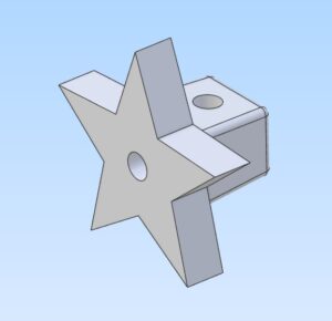
- The outer surface, where the tightening nut engages, must be clean and free of voids or inclusions.
- The front face, which interfaces with the banjo, needs a smooth, consistent surface.
- The star-shaped tips are the most visually prominent and functionally important features—and they’re the first thing anyone notices.
Brass adds another layer of difficulty. It is finicky when it comes to shrinkage and full part fill. The thin tips of the star are especially prone to incomplete fill unless the material is very hot and flows well.
Sand Choice and Material Behavior
Using phenolic or urethane sands can present challenges with brass, as the surface can erode or wash out during pour. One way around this is to use a higher-temperature binder such as sodium silicate. While effective, sodium silicate takes longer to set up and slows down production.
Whenever possible, we prefer faster-binding systems like urethane or phenolic resins. For this experiment, we chose urethane sand and evaluated how it performed with the part geometry and gating strategy.
Gating Strategy and Mold Design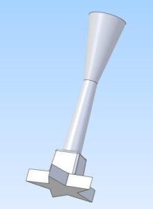
Proper fill was the most critical requirement. To achieve this, we designed a large gate feeding directly into the boss section of the part. This helped ensure that molten brass reached the thin star tips before solidifying.
With fill strategy established, the next decision was manufacturing method. There were two options:
- Solid die-cast tooling
- Sand casting
Die casting raised immediate concerns. The star tips require excellent venting, and brass is unforgiving when trapped gases form. Incomplete venting would almost certainly lead to gas bubbles and short fills at the tips.
For that reason, we chose the sand-cast approach for the initial production run.
Inflow Gates, Funnels, and Draft Challenges
When designing inflow sprues and gates, I prefer incorporating a funnel at the end of the gate. This improves metal flow but complicates sand molding because draft is required to remove the pattern cleanly.
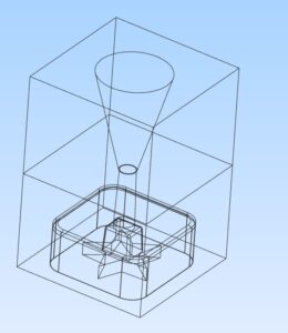
Two Mold Sets: filler cone on top and main cavity bottom
To solve this, we created two separate tool sets:
- One for the actual cavity and inline sprue
- A second for the funnel section
This allowed proper draft while maintaining the desired gate geometry.
Hybrid Tooling: Sand and Metal Combined
The outer wall of the star face was formed using a heated aluminum plate. This allowed the brass to chill quickly while producing a polished surface finish. Because of this, a sand mold for the bottom surface was unnecessary.
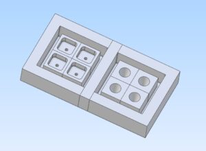
Gang Mold for upper and lower sections
We developed a four-cavity gang mold. Each individual cavity was produced using an SLA 3D printer, which gave us the fine detail required for the star geometry. CNC machining alone would have struggled to capture these details accurately and efficiently.
We’ve used this same hybrid approach successfully for items like Christmas ornaments, and it translated well to this part.
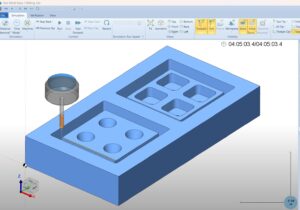
CNC Proof BobCad Simulation
CNC Machining the Mold Base
The overall mold geometry was programmed in CNC software, with the major portions machined from foam stock. A block measuring 2″ × 7″ × 13″ was placed in the CNC router.
- A ¼″ end mill was used for roughing
- Total machining time was approximately 5 hours
- BobCAD was used for toolpaths
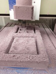
CNC Routing Foam Blanks
After roughing, finish machining was isolated to the cavity zones using a 0.015″ stepover in both X and Y directions. This stepover produces a very smooth surface with minimal sanding required. Since the fine detail comes from the SLA inserts—not the foam—the foam surface finish was not critical.
Once machined, the SLA cavities were inserted into the CNC-cut pockets.
Rubber Molds and Sand Packing
A coating of Smooth-On Mold Max 30 silicone was applied over the foam mold. While it may be tempting to use a vacuum or pressure chamber, that approach does not work well with foam (a lesson learned the hard way). Wood performs better in that scenario, but foam is easier on the CNC machine and faster to work with.
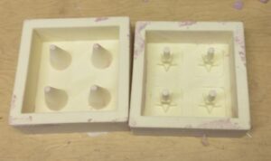
Upper fill cone (left) and main cavity with fill riser (right). 4 up cavity set up.
After a 24-hour cure, sand was vibrated into the mold cavities. Pressing the sand in by hand can deflect thin riser cones, so vibration was critical. In some cases, a wire or metal rod can be used to stiffen delicate sections, but here the stiffness of Mold Max 30 combined with the vibratory table was sufficient.
The molds were assembled and bonded using a sodium silicate–based paste glue (Core Weld NB Fast Dry) sourced from Carpenter Brothers. This sand-glue cures quickly and becomes rock-hard when exposed to molten metal.
Casting and Secondary Operations
Once cast, the parts were cleaned and prepared for secondary machining. Two holes were drilled using CNC fixtures.
The fixtures were created using 3D-printed mounts, though an aluminum fixture machined to match the part geometry would also work. The key requirement was holding the part securely enough to drill both:
- A vertical hole
- A face hole
Using a single fixture for both operations streamlined the process—one setup, one program, and one drill.
Final Thoughts
Small, intricate parts like this demand careful thought at every stage—from gating and material selection to tooling strategy and secondary operations. When done right, even low-volume runs can achieve exceptional quality without excessive tooling costs.
If this type of process interests you, we encourage you to reach out through our contact page. We specialize in small parts, small runs, and high-quality results. Our strength lies in solving complex problems efficiently and economically.