By Robert Gamble
The light bar was one of the first cast products developed for the Model T Go Kart. The original light bar made of steel tubing tended to rust, bend and crush. The original design was such that it was constructed into semi-circular formed light can sections and then flat bolt down sections.
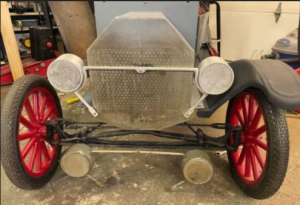
The original light bar shown below made out of rusted formed tubing. The cast version shown mounted to the Model T McDonough T-10 Tin Lizzie.
Several constructors have been brave enough to make them by hand, but it was a huge time expenditure and labor of love.
I figured that I could make a simple light bar using 3-d modeling, 3d printing and sand casting. It worked okay, as long as the mold was lined up properly. After about 5 years of making light bars and 3 sand tool iterations, it became apparent that a better way to make them was needed.
As I discuss in another article about the “groan factor,” this part had high groan factors, mainly in time consumption and sand savings. The time factor was 25 minutes to prep the mold, 25 minutes to cast the mold, 15 minutes to grind off the flashing and finalize for shipping. The sand cost was more in resources, 16 pounds of sand.
Eliminating the prep time was a big factor along with eliminating the sand mess associated with large castings in this endeavor.
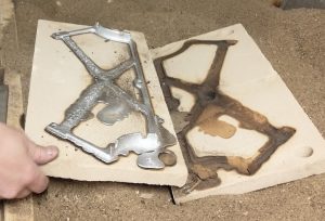
30 Minutes of Time, 16 Pounds of Sand are what it takes to get the part this far…
The Design and Development Problems
You would think with all the experience we have in casting, translating the mold design into a die cast would be simple. Not exactly. There were several elements of the design that made it difficult to cast initially, even with sand casting.
First the part is a thin cross section, getting the liquid aluminum to all these thin areas without excessive shrinkage or short shot (tool is too cold in areas), was challenging in gate layout.
Secondly, getting the part out of the mold may prove to be challenging especially with the original walls being vertical.
The final tool design put generous draft sections on the part and also ample gate channels for good fill.
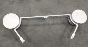
The large thin center part proved to be a tough design to make….
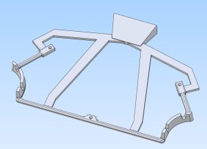
Final gate layout for the part. These gates work great for sand casting….not so much for gravity die casting, vents were needed.
| Notes on Venting: When designing a part that is going to be die cast, it is helpful to have a knowledge of where the vents are going to be placed. With gravity die casting the parts are very sensitive to flow gradients and gas pockets, because the amount of flow pressure is only the weight of the material above it, so the flow pressure is relatively low. Having generous gas venting is key as the wave of material is essentially shoving a pocket of air in front of it. That air has to go somewhere, if it does not, the part will not fill in those areas. |
Tool Manufacture and Rationale
The customer chose to go the wood sand cast route for making the final mold design. There were several complications:
1. There was uncertainty about whether the part would come off the tool
2. Would actually cooperate and come apart as needed when the cast was complete?
3. Material Tool Cost
4. Foot print of the tool was larger than the machine operating envelope
Using wood as the medium to test the waters allowed for redirection after the tool was complete and perhaps a full redesign.
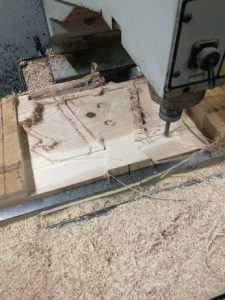
Wood tool being CNC’d out
The wood sections were custom and pushed the envelope of what the CNC machine could do as far as width and length were concerned. The initial tool size was 21 inches in length, the machine could only do 17.7. The width of the tool was around 12 preshrink but was 12.316 after full shrink was added (there was shrink for the cast part, and shrink for the casting of the mold, both had to be accounted for). The machine could only do 12.2, the actual tool design was cut back so that custom shifting of the blank around was not needed, at least in the “Y” direction.
The other conundrum was holding the blank in place on the machine, large pieces are always a challenge because they can bow or shift depending on how the blank is being clamped down.
The wood blanks came out as expected with a little sanding sealer added to keep the wood grain down on the final mold.
The actual tools used up the full 8 pound pours and probably could have used a healthy 12 pounds if we had it. That did effect some of the surface finish. In retrospect, two furnaces with 8 pound capacity probably should have been used on such large molds.
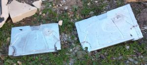
Testing the Molds
The way testing is conducted is to gain a base line to see what is happening initially. The initial part short shot and did not fill certain areas as expected, because there were gas pockets. Also the first part also shows any glaring misalignment and or tool modifications that may need urgent attention.
The alignment of the tool was excellent, however the extraction of the part took too long and as a result the part shrank and cracked before extraction.
Typically if the part is cracking it is because it is being given a tug-of-war in some manner and this means that the part needs to come out right away before full shrinkage occurs.
This part was one that kind of threw me for a loop until I forced myself to think about what was actually happening with the liquid aluminum.
The problem was short shotting. One area would not fill properly and it just did not make sense to me, until I started thinking in medical terms. Then I realized what was happening.
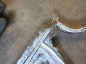
The corner was not filling, and it was not apparent why.
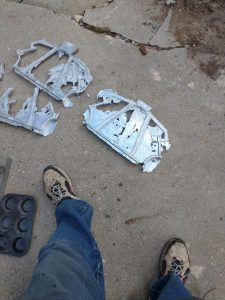
Part, after part, after part failed before success was found.
The part is essentially a tube, or an artery. Arteries only feed areas enclosed. If a bleeder happens, the flow will go there and bypass the final flow path. We call that an aneurysm. In stroke patients for example there are two types of strokes, the “clog off type” or the “bypass type.” Both can have similar results where brain tissue dies because it is not being fed blood.
In this application an area was not being fed aluminum and was not filling. I figured it needed to be vented…that didn’t really help. I figured perhaps it was chilling off, so I heated the material…that didn’t really help. I did notice that the material was leaking out so i stopped it up with sand…that didn’t really help.
Then I sat down and looked at the part and realized there was a lot of over flow all over the part. That means there is leakage. If the molten aluminum is wasting its energy going into pathways that are not the part, the actual flow path to the part will gradually shut off. And that is what was occurring, the aluminum essentially clogged off the flow path to the rest of the part and flowed to these other areas.
Because the nature of the mold design is essentially sloppy (because it was cast to begin with) there are areas of leakage, which can be acceptable for bleeding off gases. This was not the case in this non-fill area.
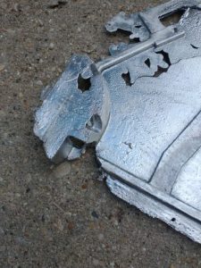
Examination of excess flow showed that the short shot was related.
There is a nifty tool used by sand casters called core-weld or what I call “sand-glue.” It is used to hold sand molds together and helps make mold assembly much easier. I have also found other uses for it as well, such as clogging off pathways for molten aluminum to go, especially on simple dies cast tools.
That is what finally solved the problem, minimized the leakage and allowed the molten aluminum to flow where it really needed to go and the part filled excellently.
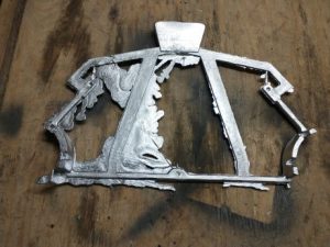
Final part with some excess flashing, but not like before. As a result the part fully filled. Core-weld or sand-glue was used to stop off the excess flow.
The 80/20 Rule Realized
In the title you noticed the “80/20” rule. Usually we think of the 80/20 rule as something that applies to sales or some other abstract concept. But the reality is that spending 20% of your time up front early troubleshooting and finding the root problem will yield 80% of the success.
I am a firm believer in wrestling a problem down, because it needs to be solved. On the other side of that problem hill is an immense 80% increase in efficiency just waiting to be realized.
The problems of sand and the time consumed in making parts will now be made much simpler. Flipping this former problem of 80% of my time making 20% of profitability is a losing proposition. Instead we flipped this on its head making this a winning proposition.
